Tailored Micro Automation
Solution Provider


| output voltage: | |
|---|---|
| Quantity: | |
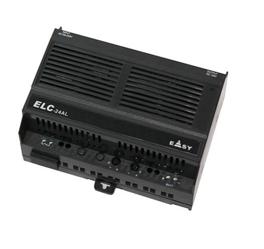
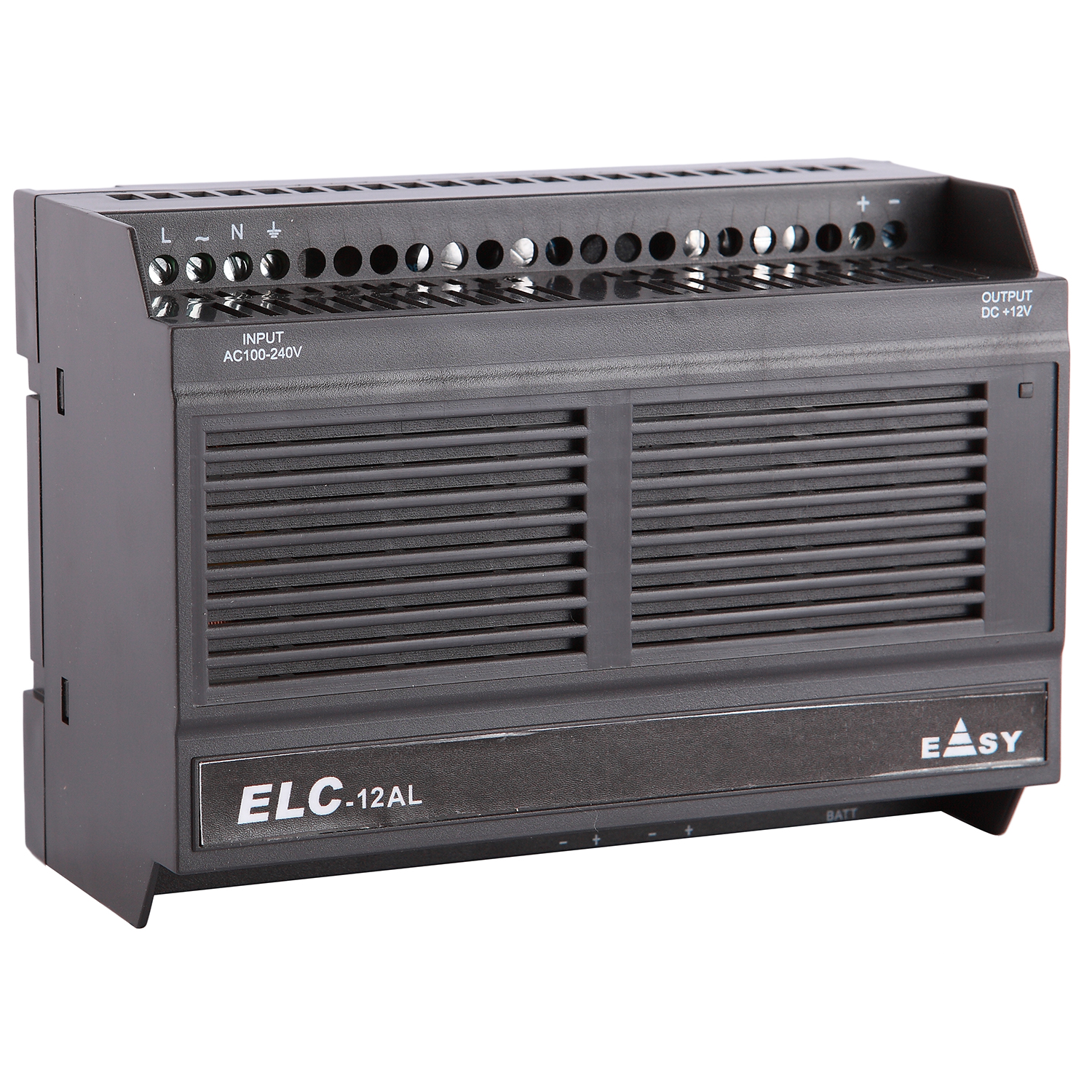
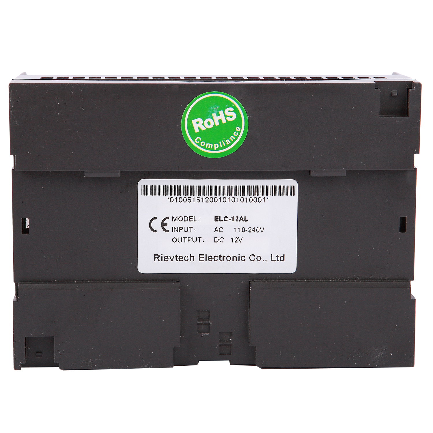
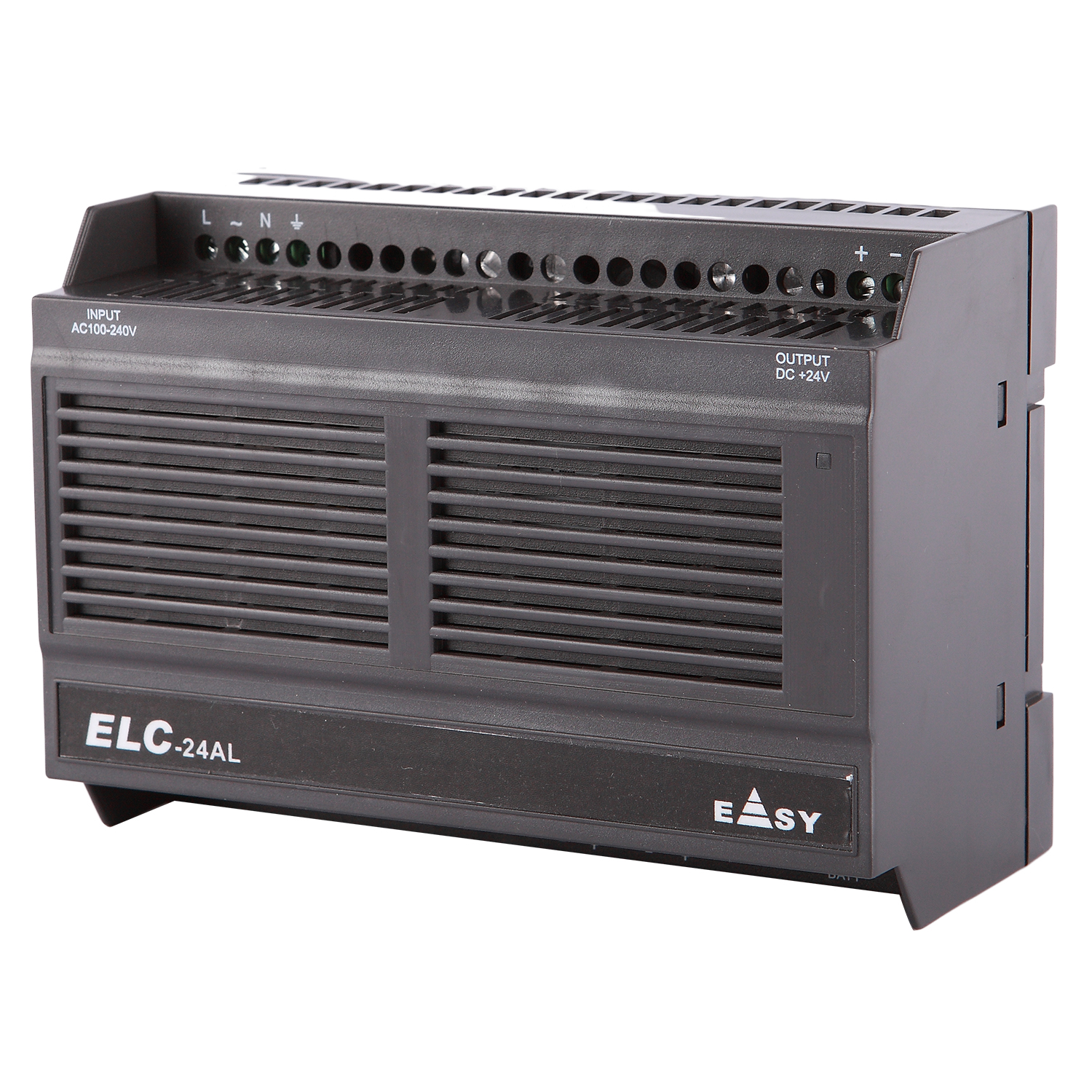
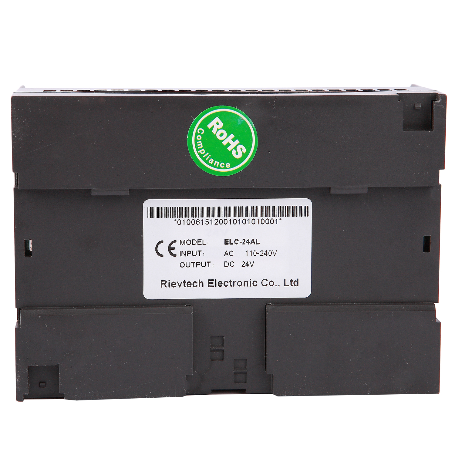
ELC-AS/AL Series Switching Power Supply highlights at a glance:
◆EMI filter condenser
◆Input frequency:47~63HZ
◆Output voltage stability:0.5%
◆Can be used for DIN rail mounting (EN50022-35)
◆Wide range voltage input(100~240VAC/140~340VDC)
◆Ripple voltage tolerance range(85-264VAC/120-370VDC)
◆Output voltage fine adjustment range(-5% ~+10%),adjusting potentiometer V
◆Have the function of soft-start(to limit the peak current of start and the pressure of the voltage to the components)
◆The current of the load can be roughly adjusted (Means the maximum protective current of the load, adjusting
potentiometer A)
◆Effective:>75%
◆Insulation voltage endurance:>1.5KV
◆Power supply output with the LED indicator
◆Ripple:≤150mVp-p
◆Have the short circuit and over-load protection.(Short circuit protection means miss-connect the output voltage in short,
after disconnect, the output will be renew; Over-load protection: 105%-135%)
◆ With the UPS function. (External-connected battery, provide with the UPS by the power supply and the battery.)
◆With the remote control function. (By the switch control the having and non-having of the output voltage).
◆With the over-heat protection function.(The main control CMOS chip stops output when the temperature is beyond 135C
and the output will renew automatically when the temperature reduces.