

PR-26DC-DAI-RT-2G
RIEVTECH
| Availability: | |
|---|---|
| Quantity: | |
Model:PR-26DC-DAI-RT-2G
Small in size, Big in features
LCD Screen
-I/O status,user configurable messages(up to 64) with dynamic data,FBD program monitor and controls.
-Record on an alarm page and display the exact alarm occurrence time.
-Parameters can be modified in the alarming message.
Keypad
-With the programmable keys,you can reduce the number of used pushbuttons.
-Modify parameters via keypad panel without downloading new program.
RS485 port
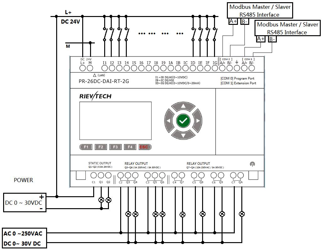
-Built-in RS485 port with galvanic isolation for connection of the PLC with Modbus networks.
-Can work both as a master and as a slave device.
Ethernet port
-The built-in Ethernet port allows you to upload/download programs to the PLC,configure it,take advantage of the built-in web server,connect to other devices and more.
-The PLC can work as TCP server and TCP client at the same time,and also it can work as UDP server or UDP client as well.
Expansion port(up tp 16 modules)
-A wide variety of expansion modules such as Digital I/O, Analog I/O and communication modules are avarilable to create the application you need.
Micro SD Card slot for data-logging
-Data-logging is the process of collecting,in real time, determined process parameters such as conditions,values as well as the time that said information is collected,or noted.
MQTT protocol support
-Pub/Sub messaging protocol typically used to connect hardware to the Cloud, No more need for inermediate Gateway devices.
GENERAL SPECIFICATIONS
◆Timers: 1024
◆Counters: 1024
◆Function Blocks: 1024
◆Operation temp.: -20 ℃ - 55 ℃
◆Storage: -40 ℃ - 70 ℃
◆Protection: IP20 (Non-waterproof)
◆RTC accuracy: MAX ±2S/day
◆RTC Backup at 25 ℃: 20 days
◆Program and settings Backup: 10 years
◆Data Power-off retentivity: 10 years
◆Modify parameters via keypad LCD: YES
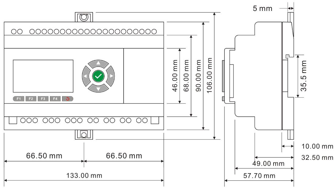
◆Dimensions: 133*90*60(Unit:mm)
◆Certificate:
◆Installation: 35-DIN rail or screw for installation
◆Expansion capacity: 16 modules (PR-E-16)
◆Password protection: 4-digit number password protection or disable program upload function
◆Communication interface: 1 RS232 Port (COM0) & 1 RS485 port (COM1 external) available via optional accessory,
2 built- in RS485 (C0M2, C0M3), 1Ethernet port.
◆Communication protocol: Modbus RTU/ASCII, Modbus TCP
Technical Index
| Power supply: | |
| Nominal voltage | DC 24V |
| Operating limits | DC 20.4-28.8V |
| Immunity from micro power cuts | Typ.5 ms |
| Max. Startup current | Max. 0.3A |
| Max. absorbed power | 10W |
| Protection against polarity inversions | Yes |
| Input parameters: | |
| Input No | 16 ( I1-IG) |
| Digital input | 16 ( I1-IG) |
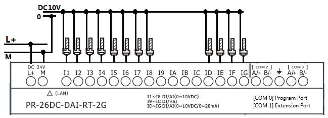
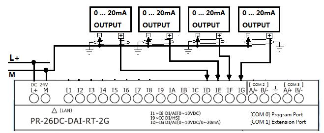
| Analogue input | 8 ( I1-I8)(0..10V DC) +4(ID-IG)(0...20mA OR 0..10V DC) |
| Digital input and analog inputs (0...10V)10bits( I1-I8 ) | |
| Inputs used as digital inputs( I1-I8 ) | |
| Input voltage | DC0-28.8V |
| Input signal0 | < 5V DC;<0.08mA |
| Input signal1 | > 8 V DC;>0.12mA |
| Input current | 0.16mA @ 10.8V dc 0.18mA @ 12.0 V dc 0.34mA @ 24 V dc 0.41mA @ 28.8 V dc |
| Response time | 0 to 1 :Typ. 10.5 ms ;1 to 0 :Typ. 1.5 ms |
| Maximum counting frequency | Typ.:4 HZ |
| Sensor type | Contact or 3-wire PNP |
| Input type | Resistive |
| Isolation between power supply and inputs | None |
| Isolation between inputs | None |
| Inputs used as analog inputs(0..10V)( I1-I8 ) | |
| Measurement range | DC 0---10V |
| Input impedance | Min, 24KΩ; Max. 72KΩ |
| Input voltage | 28.8 V DC max |
| Resolution | 10bit ,0.01V |
| Accuracy at 25 °C | ± (Max.0.02)V |
| Accuracy at 55 °C | ± (Max.0.04)V |
| Isolation between analog channel and power supply | None |
| Cable length | 10 m max. shielded and twisted |
| Digital and high speed inputs(I9--IC) | |
| Digital inputs( I9-IC ) | |
| Input voltage | DC0-28.8V |
| Input signal0 | < 5V DC; <1mA |
| Input signal1 | > 8 V DC;>1.6mA |
| Input current | 2.1mA @ 10.8V dc 2.3mA @ 12.0 V dc 4.6 mA @ 24 V dc 5.5 mA @ 28.8 V dc |
| Response time | 0 to 1 :<1 ms ;1 to 0 :<1 ms |
| High speed inputs( I9-IC ) | |
| Maximum counting frequency | 60kHZ(I9--IC) |
| Digital and analog(0--10V)&analog(0...20mA)(ID-IG) | |
| Inputs used as digital inputs( ID-IG ) | |
| Input voltage | DC0-28.8V |
| Input signal0 | < 5V DC;<0.08mA |
| Input signal1 | > 8 V DC;>0.12mA |
| Input current | 0.16mA @ 10.8V dc 0.18mA @ 12.0 V dc 0.34mA @ 24 V dc 0.41mA @ 28.8 V dc |
| Response time | 0 to 1 :Typ. 10.5 ms ;1 to 0 :Typ. 1.5 ms |
| Maximum counting frequency | Typ.:4 HZ |
| Sensor type | Contact or 3-wire PNP |
| Input type | Resistive |
| Isolation between power supply and inputs | None |
| Isolation between inputs | None |
| Inputs used as analog inputs(0..10V)( ID-IG ) | |
| Measurement range | DC 0---10V |
| Input impedance | Min, 24KΩ; Max. 72KΩ |
| Input voltage | 28.8 V DC max |
| Resolution | 10bit ,0.01V |
| Accuracy at 25 °C | ± (Max.0.02)V |
| Accuracy at 55 °C | ± (Max.0.04)V |
| Isolation between analog channel and power supply | None |
| Cable length | 10 m max. shielded and twisted |
| Input signal0 | < 5V DC;<0.08mA |
| Input signal1 | > 8 V DC;>0.12mA |
| Input current | 0.16mA @ 10.8V dc 0.18mA @ 12.0 V dc 0.34mA @ 24 V dc 0.41mA @ 28.8 V dc |
| Response time | 0 to 1 :Typ. 10.5 ms ;1 to 0 :Typ. 1.5 ms |
| Sensor type | Contact or 3-wire PNP |
| Input type | Resistive |
| Isolation between power supply and inputs | None |
| Isolation between inputs | None |
| Inputs used as analog inputs(0..20mA)( ID-IG ) | |
| Analogue signal | 0/4….20mA current |
| Input impedance | 260Ω |
| Resolution | 0.02mA |
| Accuracy at 25 °C | 0.05mA |
| Cycle time for analog value generation | Typ. 50 ms |
| Protection against polarity inversions | yes |
| Overvoltage protection | Yes, if the input voltage is >6.5V, this one is automatically switched on 0--10V configuration |
| Isolation between power supply and inputs | No |
| Cable length | <=30M with shielded twisted cable(sensor not isolated) |
| | |
| Output | |
| Digital/Transistor output(PNP) - Q1,Q2 | |
| Breaking voltage | DC 5--30V |
| Nominal voltage | ≤ Supply voltage |
| Nominal current | Max. 0.3 A per channel |
| Max. breaking current | 0.65 A |
| Voltage drop | < 2 V for I = 0.3 A (at state 1) |
| Response time | Make ≤ 1 ms Release ≤ 1 ms |
| Frequency (Hz) | resistive load : 10 Hz inductive load : 0.5 Hz |
| Built-in protections | Against overloads and short-circuits: No Against overvoltages (*): No |
| Galvanic isolation | None |
| PWM frequency | 10K HZ |
| PWM cyclic ratio | 0 to 100 % |
| PWM accuracy at 120Hz | < 0.5 % (20 % ➞ 80 %) load at 10 mA |
| Max. Breaking current PWM | 50 mA |
| Max. cable length PWM | 20m |
| 5A Relay 4 outputs from Q3 to Q6 | |
| Max. breaking voltage | CE:AC 250 V/DC 30 V 5A UL:AC 250 V/DC 30 V 3A |
| Electrical durability Expectancy | 105 Operations at Rated Resistive Load |
| Mechanical life | 107 Operations at No Load condition |
| Response time | Operate Time: 15 mSec. Max. Release Time: 10 mSec. Max. |
| Built-in protections | Against short-circuits: None Against overvoltages and overloads: None |
| 10A Relay 4 outputs from Q7 to QA | |
| Max. breaking voltage | CE:AC 250 V/DC 30 V 10A UL:AC 250 V/DC 28 V 5A |
| Max. Allowable Power Force | 1250VA |
| Electrical durability Expectancy | 105 Operations at Rated Resistive Load |
| Mechanical life | 107 Operations at No Load condition |
| Response time | Operate Time: 15 mSec. Max. Release Time: 10 mSec. Max. |
| Built-in protections | Against short-circuits: None Against overvoltages and overloads: None |
| Communication ports parameters: | |
| COM0_TTL port | Can be used as program port with PR-RS232&PR-USB; Also can be convert to RS232 port with PR-RS232 Can be convert to RS485 port with PRO-RS485 Note:Need move away the expand cover to use it Can be used as modbus master or slave |
| Built-in RS485 COM2 | 1 built-in RS485 port (Terminal A+,B-) Can be used as modbus master or slave |
| Built-in RS485 COM3 | 1 built-in RS485 port (Terminal A+,B-) Can be used as modbus master or slave |
| Ext RS485 COM1 | Need use with PR-E-RS485 module Can be used as modbus master or slave |
| Ethernet port: | Built-In(10M/100M), 1.Can be used as program or communication 2.Can be used as modbus master or slave |
| Monitoring webserver page | Yes |
| Xlogic<--->Xlogic(by Ethernet) | 1 xlogic works as tcp server can connect with 8 tcp client xlogics or other tcp devices. |
| Xlogic<--->Ethernet/Internet: | 1 xlogic works as TCP clients can connect with 8 different tcp servers separately in maximum |
| GSM parameter | |
| Type of mobile wireless service | SMS, GPRS |
| Operating frequency | 850MHz,900MHz,1800MHz,1900MHz, |
| for GPRS transmission / with downlink / maximum for GPRS transmission / with uplink / maximum | 80 kbit/s 40 kbit/s |
| | |
| Other parameter | |
| Weight | Approx.400g |
| PR-26 Series CPU | |||||||||
| Model | Supply volt | Inputs | Outputs | High-speed count | PWM | 4G/GSM/GPRS | Ethernet port | MQTT | |
| PR-26AC-R-N | AC110~240V | I1-IG : 16 DI AC ; | Q1--Q6(RELAY 5A 250VAC / 3A 30VDC) + Q7--QA(RELAY 10A 250VAC /5A 30VDC) | None | NO | NO | YES | NO | YES |
| PR-26DC-DAI-RA-N | DC24V | I1-I8:8DI/AI(0-10V signal)+I9-IC:4DI/HSI+ID-IG:4 DI/AI(0-10V/0-20mA signal); | Q1-Q2(0-20mA/0-10V)+Q3-Q6(RELAY 5A 250VAC/3A 30VDC)+Q7-QA(RELAY 10A 250VAC/5A 30VDC) | 4 routers(I9-IC)(60KHZ) | NO | NO | YES | NO | YES |
| PR-26DC-DAI-RT-N | DC24V | I1-I8:8DI/AI(0-10V signal)+I9-IC:4DI/HSI+ID-IG:4 DI/AI(0-10V/0-20mA signal); | Q1-Q2(0-20mA/0-10V)+Q3-Q6(RELAY 5A 250VAC/3A 30VDC)+Q7-QA(RELAY 10A 250VAC/5A 30VDC) | 4 routers(I9-IC)(60KHZ) | 2 (Q1--Q2)(10KHZ) | NO | YES | NO | YES |
| PR-26DC-DAI-RT-2G | DC24V | I1-I8:8DI/AI(0-10V signal)+I9-IC:4DI/HSI+ID-IG:4 DI/AI(0-10V/0-20mA signal); | Q1-Q2(0-20mA/0-10V)+Q3-Q6(RELAY 5A 250VAC/3A 30VDC)+Q7-QA(RELAY 10A 250VAC/5A 30VDC) | 4 routers(I9-IC)(60KHZ) | 2 (Q1--Q2)(10KHZ) | 2G/GSM | YES | NO | YES |
| PR-26DC-DAI-RT-4G | DC24V | I1-I8:8DI/AI(0-10V signal)+I9-IC:4DI/HSI+ID-IG:4 DI/AI(0-10V/0-20mA signal); | Q1-Q2(0-20mA/0-10V)+Q3-Q6(RELAY 5A 250VAC/3A 30VDC)+Q7-QA(RELAY 10A 250VAC/5A 30VDC) | 4 routers(I9-IC)(60KHZ) | 2 (Q1--Q2)(10KHZ) | 2G/4G/GSM | YES | YES | YES |
| PR-26DC-DAI-RT-WIFI | DC24V | I1-I8:8DI/AI(0-10V signal)+I9-IC:4DI/HSI+ID-IG:4 DI/AI(0-10V/0-20mA signal); | Q1-Q2(0-20mA/0-10V)+Q3-Q6(RELAY 5A 250VAC/3A 30VDC)+Q7-QA(RELAY 10A 250VAC/5A 30VDC) | 4 routers(I9-IC)(60KHZ) | 2 (Q1--Q2)(10KHZ) | NO | YES | NO | YES |
| PR-26DC-DAI-RT-4GWIFI | DC24V | I1-I8:8DI/AI(0-10V signal)+I9-IC:4DI/HSI+ID-IG:4 DI/AI(0-10V/0-20mA signal); | Q1-Q2(0-20mA/0-10V)+Q3-Q6(RELAY 5A 250VAC/3A 30VDC)+Q7-QA(RELAY 10A 250VAC/5A 30VDC) | 4 routers(I9-IC)(60KHZ) | 2 (Q1--Q2)(10KHZ) | 2G/4G/GSM | YES | YES | YES |
Installation Dimensions


Installation Dimensions


