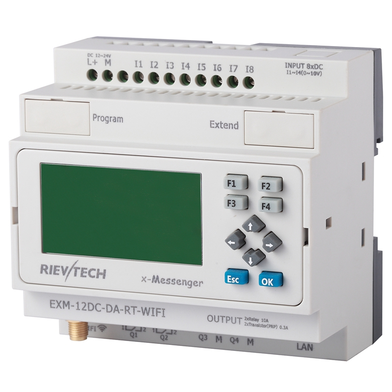
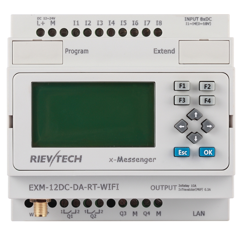
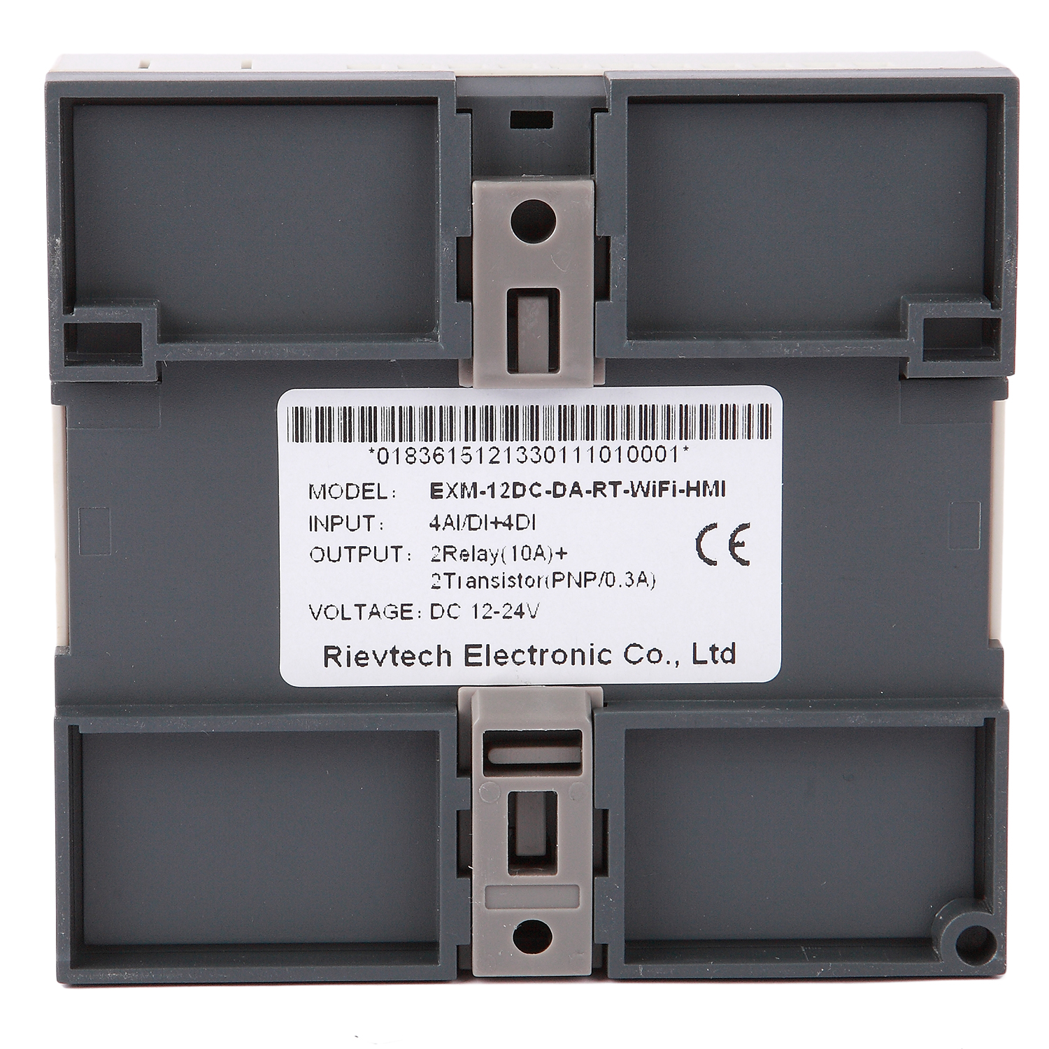
| Power supply: |
| Nominal voltage | DC 12-24V |
| Operating limits | DC 10.8-28.8V |
| Immunity from micro power cuts | Typ.5 ms |
| Max. Startup current | Max. 0.25A |
| Max. absorbed power | 3.5 W (10.8V dc) ; 4 W (28.8V dc) |
| Protection against polarity inversions | Yes |
| Input parameters: |
| Input No | 8 ( I1-I8 ) |
| Digital input | 8 ( I1-I8 ) |
| Analogue input | 4 ( I1-I4)(0..10V DC) |
| Digital inputs( I5-I8 ) |
| Input voltage | DC0-28.8V |
| Input signal0 | < 5V DC; <1mA |
| Input signal1 | > 8 V DC;>1.7mA |
| Input current | 2.3mA @ 10.8V dc
2.6mA @ 12.0 V dc
5.2 mA @ 24 V dc
6.3 mA @ 28.8 V dc |
| Response time | 0 to 1 :<1 ms ;1 to 0 :<1 ms |
| Maximum counting frequency | 60k Hz(I7--I8) |
| Sensor type | Contact or 3-wire PNP |
| Input type | Resistive |
| Isolation between power supply and inputs | None |
| Isolation between inputs | None |
| Inputs used as digital inputs( I1-I4 ) |
| Input voltage | DC0-28.8V |
| Input signal0 | < 5V DC;<0.1mA |
| Input signal1 | > 8 V DC;>0.3mA |
| Input current | 0.4mA @ 10.8V dc
0.5mA @ 12.0 V dc
1.2mA @ 24 V dc
1.5mA @ 28.8 V dc |
| Response time | 0 to 1 :Typ. 1.5 ms ;1 to 0 :Typ. 1.5 ms |
| Maximum counting frequency | Typ.:4 HZ |
| Sensor type | Contact or 3-wire PNP |
| Input type | Resistive |
| Isolation between power supply and inputs | None |
| Isolation between inputs | None |
| Inputs used as analog inputs( I1-I4 ) |
| Measurement range | DC 0---10V |
| Input impedance | Min, 24KΩ ; Max. 72KΩ |
| Input voltage | 28.8 V DC max |
| Resolution | 10bit ,0.01V |
| Accuracy at 25 °C | ± (Max.0.02)V |
| Accuracy at 55 °C | ± (Max.0.04)V |
| Isolation between analog channel and power supply | None |
| Cable length | 10 m max. shielded and twisted |
| Output parameters: |
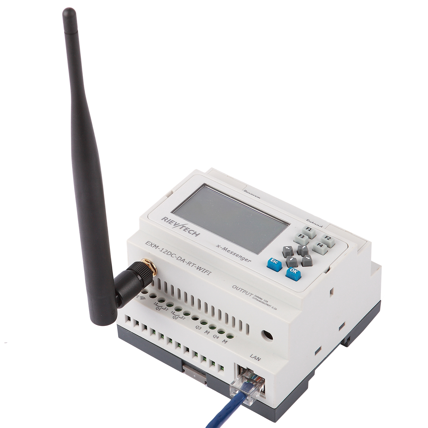
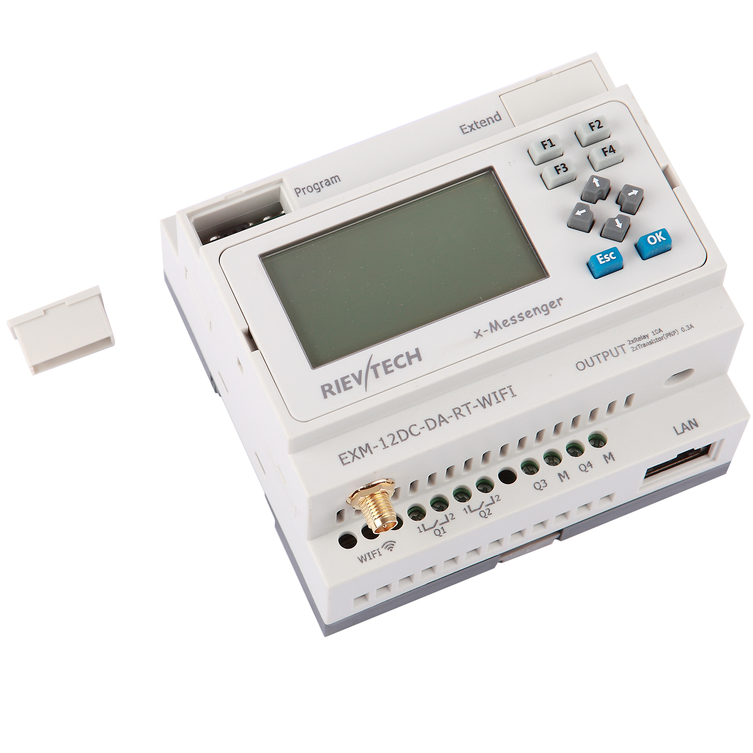
| Output No. | 4 (Q1-Q4) |
| Output type | 2Relay output +2 Transistor(PNP) output |
| Continuous current | (Q1-Q2)Resistive load 10A/Inductive load 2A
(Q3-Q4) Max. 0.3 A per channel |
| Max. breaking voltage | (Q1-Q2) AC 250 V DC 30 V
(Q3-Q4) ≤ Supply voltage |
| Max. Allowable Power Force | (Q1-Q2)1250VA 300W
(Q3-Q4) 9 W |
| Electrical durability Expectancy | 105 Operations at Rated Resistive Load |
| Mechanical life | 107 Operations at No Load condition |
| Response time | Operate Time : 15 mSec. Max.
Release Time : 10 mSec. Max. |
| Built-in protections | Against overloads and short-circuits: No
Against overvoltages (*): No |
| Galvanic isolation | None |
| PWM frequency(Q3-Q4) | 1K HZ |
| PWM cyclic ratio(Q3-Q4) | 0 to 100 % |
| PWM accuracy at 120Hz(Q3-Q4) | < 0.5 % (20 % ➞ 80 %) load at 10 mA |
| Max. Breaking current PWM(Q3-Q4) | 50 mA |
| Switch frequency: |
| Mechanism | 10Hz |
| Resistor/light load | 2Hz |
| Sensitive load | 0.5Hz |
| Built-in wireless parameters: |
| Support 802.11b/g/n wireless standards |
| Support TCP/IP/UDP network protocols |
| Support work as STA/AP mode |
| Support Router/Bridge mode networking |
| Support Transparent/Agreement Transmission Mode(Transparent used by EXM CPU) |
| Support Friendly Web Configuration Page or configuration by eSmsconfig |
| Outdoor 100m with 3dBi antenna and indoor 40m |
| FCC /CE Certificated |
| Other parameters: |
| Ethernet port: | Built-In(10M/100M) |
| Xlogic<--->Xlogic(byWifit) | 1 xlogic works as server can connect 32 client xlogics. |
| Xlogic<--->Etherne/Internet: | xlogic works as TCP server or TCP client |
| Weight | Approx.300g |